Laser Leveller, Laser Bucket Scrapper, Laser Machine Control, laser Grading Machine all these terms refers to one class of equipments. Locally they call it Computer Godi, Computer manja/Karaha in india. This Machine first introduced in 1997 by Trimble Navigations through its distributer SPLTech Pvt ltd. Now these machines are produced by number of companies and sold in india. There are few local manufacturers too.
Why we Need Laser Leveller?
(3 Year ago i was interviewed by retired BARC scientist, i explained him it but after 15 minutes of explaination he didnt got anything but the nontech HR understood everything then he explained the same now somehow he was still confused but nodded all because of his ego)
Our eye cant tell us everything right always, sometimes we cant judge two ground levels relative height just by looking. Similar to the magnetic hill in ladakh there are regions with small variation around us which can be observed when they filled with water. Here we need some instrument to measure actual relative height.
How It works ?
Laser Reference Plane, yes this is the key behind the whole technique. We create a virtual disc of light with a Rotating Laser beam. The disc of light is made perfectly horizontal by adjusting the position of Light source by electronic system with spirit levels. Here we are laser so the light beam is perfectly straight and narrow with no or negligible spread. So we have perfect light disc of light with 4-5mm vertical width
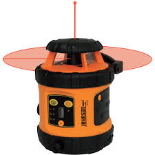
Laser Plane Visualisation of Virtual Light Plane
This light plane intensity decreases with distance from the center and usable upto 500mtr (4/5miliWatt 650nm Source)
Now you have a reference level all across your field now at any point if you want measure relative height of ground, you can easily calculate it from the distance from the lightplane. Now if you want a machine to do it, the machine should have some sensor to detect vertical height of the light disc.
 Components:
1. Transmitter:
Mostly they use a semiconductor laser of 650nm which rotates at a programbale speed og 300/600 RPM. The Laser source i.e. the diode is placed on special mechanical assembly which is shock compensated and automatically balanced with electronically sensed spirit levels(Newer manufacturers are using Acceleration/Gyration sensors). The diode throws light upwards which is then partially reflected by a prism. (This mechanism helps the transmitter for vertical measurements required for civil construction workers, vertical beam is useless for grading application)
The beam width of most transmitters is 5 to 7mm.
The transmitter is powered by easy replacable rechargeable batteries of 4000mAH which lasts for atleast 4/5 working hours.
2. Laser receiver
Laser receiver is assembly of Photodiode array, amplifier comparator signal conditioners and Logic Unit. The photodiodes are mounted in a vertical strip each set of photo diode in same vertcal position are grouped together. This unit is most important part of the system.
Although we are using laser but if you compare 5 mili watt laser at 400 meter distance from source compared to normal diffused daylight is not distinguishable. We cant use high intensity laser beam for user safety.
DeadBand/Threshold band: This is the minimum detectable change in height through the receiver. The level of accuracy depends on this. Some of the manufacturers provide a programmable Deadband for their instruments.
Protocol: Most of the receivers use CAN for communication between The Control Box and receiver. Some use 4-20mA current loop for signals.
3. Control Box:
This component is a medium sized box attached to the vehicle just beside the operator seat. This component is also acts as junction box and control panel.
A display attached to the box for monitoring of proper function of the instrument. (there are high probability of improper function during operation due to natural causes like wind so operator need to monitor it although the system is automatic.
Why we Need Laser Leveller?
(3 Year ago i was interviewed by retired BARC scientist, i explained him it but after 15 minutes of explaination he didnt got anything but the nontech HR understood everything then he explained the same now somehow he was still confused but nodded all because of his ego)
Our eye cant tell us everything right always, sometimes we cant judge two ground levels relative height just by looking. Similar to the magnetic hill in ladakh there are regions with small variation around us which can be observed when they filled with water. Here we need some instrument to measure actual relative height.
How It works ?
Laser Reference Plane, yes this is the key behind the whole technique. We create a virtual disc of light with a Rotating Laser beam. The disc of light is made perfectly horizontal by adjusting the position of Light source by electronic system with spirit levels. Here we are laser so the light beam is perfectly straight and narrow with no or negligible spread. So we have perfect light disc of light with 4-5mm vertical width
Laser Plane Visualisation of Virtual Light Plane
This light plane intensity decreases with distance from the center and usable upto 500mtr (4/5miliWatt 650nm Source)
Now you have a reference level all across your field now at any point if you want measure relative height of ground, you can easily calculate it from the distance from the lightplane. Now if you want a machine to do it, the machine should have some sensor to detect vertical height of the light disc.

1. Transmitter:
Mostly they use a semiconductor laser of 650nm which rotates at a programbale speed og 300/600 RPM. The Laser source i.e. the diode is placed on special mechanical assembly which is shock compensated and automatically balanced with electronically sensed spirit levels(Newer manufacturers are using Acceleration/Gyration sensors). The diode throws light upwards which is then partially reflected by a prism. (This mechanism helps the transmitter for vertical measurements required for civil construction workers, vertical beam is useless for grading application)
The beam width of most transmitters is 5 to 7mm.
The transmitter is powered by easy replacable rechargeable batteries of 4000mAH which lasts for atleast 4/5 working hours.
2. Laser receiver
Laser receiver is assembly of Photodiode array, amplifier comparator signal conditioners and Logic Unit. The photodiodes are mounted in a vertical strip each set of photo diode in same vertcal position are grouped together. This unit is most important part of the system.
Although we are using laser but if you compare 5 mili watt laser at 400 meter distance from source compared to normal diffused daylight is not distinguishable. We cant use high intensity laser beam for user safety.
DeadBand/Threshold band: This is the minimum detectable change in height through the receiver. The level of accuracy depends on this. Some of the manufacturers provide a programmable Deadband for their instruments.
Protocol: Most of the receivers use CAN for communication between The Control Box and receiver. Some use 4-20mA current loop for signals.
3. Control Box:
This component is a medium sized box attached to the vehicle just beside the operator seat. This component is also acts as junction box and control panel.
A display attached to the box for monitoring of proper function of the instrument. (there are high probability of improper function during operation due to natural causes like wind so operator need to monitor it although the system is automatic.
/(NIR+VIS)")
/(NIR+RED)")


